Non Volatile Technologies Pty Ltd
BALLINA AUSTRALIA 2478 (ABN 96 078 508 264) Ph:+61 2 9016 4695
"Helping others to have a future assures our own."
- Home
- Past Projects
Silencer R&D
Non Volatile Technologies Pty Ltd
BALLINA AUSTRALIA 2478 (ABN 96 078 508 264) Ph:+61 2 9016 4695
"Helping others to have a future assures our own."
Silencer R&D
|
RESEARCH INTO AND DEVELOPMENT OF A NOISE SUPPRESSOR FOR A SNIPER RIFLE FIRING HIGH VELOCITY ROUNDS 
Fig 1. Developed silencer's Method of Operation (click to enlarge)

Fig 2. Final Prototype partially disassembled SYNOPSIS Why research silencers? In 1972, as part of my Engineering Degree, I conducted research into noise suppressors for rifles firing high velocity (supersonic) rounds. The product of that research was a silencer design that performed competitively, in terms of noise attenuation, with conventional silencers but only protruded approximately 2 inches, 50 millimetres, beyond the muzzle of the rifle compared to a conventional silencer's 12 inches (300 millimetres). Because of their length and the possibility of misalignment resulting in a bullet striking a baffle, conventional silencers required the services of a fitter armourer, or suitably trained person, to fit them. The experimental silencer, because it extended very little distance past the muzzle and only had one baffle, did not.This silencer utilised what I called a "fluidic diode"; "fluidic" because gas, at the pressures present in a gun barrel, behaves like a fluid. The fluidic diode inhibited gas flow in the forwards direction and provided an escape route for this gas into a chamber running back along the barrel where decompression of the gas could occur before it was finally vented to the outside atmosphere. Why suppress the noise of weapons firing supersonic rounds? In my final year of Mechanical Engineering, 1972, I wanted to continue to work on my rifle but that was ruled out as being too ambitious and beyond the capabilities of the engineering lab. Of all the possibilities the one which was finally selected was the development of a noise suppressor for a rifle firing supersonic rounds. My motivation for doing this was two-fold:
What happened!?! The idea was forwarded to Army Design Establishment under the Army Suggestion Scheme and, just as with the RMC No2 Rifle, the same personalities came to the conclusion the idea did not merit further research or development.This design is now used in a number of silencers incorporated into sniper rifles firing supersonic rounds; one such rifle the Australian Defence Force now buys from an overseas company. |
Fig 3. Typical Long Noise Suppressor of the 1970's. 
Fig 4. Typical Method of Measuring Noise emanating from the Muzzle of a Weapon. INTRODUCTION Background Initial Motivation. My primary motivation for developing a noise suppressor for the L1A1 and M60 Machine Gun was to protect the hearing of firers. Hearing impairment is a significant handicap for a soldier employed in a defensive position; especially at night. As research began it became evident to me that a weapon with a suppressed report was more difficult to locate using the "crack and thump" method. Indeed, when shot at by a supersonic round from a weapon fitted with an effective noise suppressor, the effect was to cause the person being shot at to judge that the firer was in the wrong direction. This would cause them to take up an ineffective fire position rendering them especially vulnerable to the accurate fire delivered by a sniper. Preliminary Investigation. Before commencing my own research and experimentation, I obtained a number of books on silencers as well as some papers from the Rockford Arsenal Research Center. There were three areas of interest:
How Noise Suppressors Work. Noise Suppressors work by delaying the exit of gas from the muzzle of a weapon, usually by employing a series of baffles, thereby reducing the intensity of the shock wave that results. In 1970, noise suppressors for high powered weapons were a rarity. Silencers. In general, noise suppressors (also called Silencers) were used for sub-machine guns firing sub-sonic rounds and, in those designs, gas was tapped off through holes in the barrel. They also were used for hunting vermin such as rabbits using sub-sonic .22 ammunition. I had used such a weapon in South Australia where they were legal and found them to be very effective for shooting large numbers of rabbits. The report from that weapon was very subdued to less than that of an air-rifle. In Vietnam, the US Army used noise suppressors to great effect on rifles firing high-velocity 7.62mm rounds but the noise suppressors extended a long way beyond the muzzle of the weapon. As such, they had the potential to affect the jump of the barrel and added substantially to the weapon's overall weight.(See Figure 3) Additionally, fitting these noise suppressors required a gauge to ensure that the projectile would not collide with the baffles. Concept of Research Method of Conducting Research. To conduct research into noise suppressors one must, obviously, measure the noise emanating from the muzzle of a weapon and the direction of this noise. The conventional way this had been done in the past was to plot isobars, that is, lines of equal pressure, as per Figure 4, which is not unlike contours on a map. Initial Design Thoughts. I therefore directed my attention to investigating if it was possible to construct an effective silencer that would be lightweight and not protrude any further beyond the muzzle of a weapon than a conventional flash eliminator. This meant I was looking to having a tube, possibly concentric to the weapon's barrel, running back towards the firer from the muzzle. One obvious way of doing this was to simply have holes in the barrel through which the high pressure gas could escape into a sealed or partially sealed concentric tube. This would result in some attenuation of the noise but would also reduce the muzzle velocity and hence lethality and range of the round. If there were to be a tapping off of the gas, it had to be as close to the muzzle as possible. It was also necessary there still be expansion chambers forward of the muzzle but these would not need to be as large as was the case with a more conventional design of silencer. I decided also to see if there were ways by which I could cause the gas emanating from the muzzle to disperse so that it would collide with any baffles placed in the path of the bullet. |
|
Initial Preparation 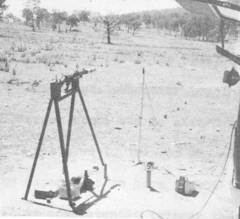
Fig 5. Test rig for measuring blast patterns 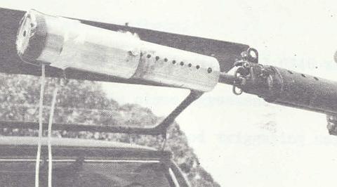
Fig 6. One method used to trigger the CRO The Microphone. It was obvious from the outset I would need to measure accurately the noise emanating from the muzzle of a weapon and that the microphone to do this would have to have a very quick response time as well as be capable of standing a very severe shock wave. For this purpose, I chose a Brüel & Kjær(B&K) 1/8" capacitive microphone. It had a frequency response up to 20,000 Hz and could stand 180dB overpressure. The Test Stand. As the main intention was to develop a means of suppressing the noise of a rifle such that it would not damage the ears of the firer, the rifle chosen for this experimentation was the standard issue 7.62mm L1A1, Self Loading Rifle(SLR). To hold the rifle, I had the engineering laboratory workshop, under Mr Bourgoine, construct a rest made out of appropriately sized channel. Helping me with this was Mr Fulvio Peliago and Mr Don Pepper. Everyone was very supportive, full of ideas and very skilled craftsmen. They were great people to work with. The test stand is shown in Figure 5 with the B&K microphone to its front at 1 o'clock. All equipment was transported to the range using a Volkswagen Kombivan; the back door of which can be just seen in the photo. The Cathode Ray Oscilloscope(CRO) and Polaroid Camera. The output from the microphone had to be displayed on a CRO and the images recorded on photographic film. It was preferable the film be polaroid so that it would allow me to view the results immediately and take additional pictures as necessary if there was a mishap. To record the traces on the CRO required that I use 1,000ASA Polaroid film and this was only available from the US DoD. To obtain the film, it was necessary I agree to share all of the research with the US. Given the US was and still is an important ally of Australia, this was not a problem. Triggering the CRO. The polaroid camera was housed in a special light-proof adaptor that fitted to the front of the CRO, as shown in Figure 6. To take a photo of the sweep of the CRO, the shutter was held open, the rifle fired and the CRO triggered at a precise moment before the shock wave reached the microphone; it being positioned 1 metre from the barrel of the rifle. Initially, in order to trigger the CRO, a wire was placed across the exit of the projectile such that the wire would be blown apart. After a few experiments it was found that precise triggering could be achieved by taping a simple, inexpensive, piezo-electric earpiece to the barrel of the rifle. Besides being simple, this had the added benefit of ensuring the blast emanating from the muzzle was in no way distorted by any obstruction no matter how seemingly trivial it might appear. |
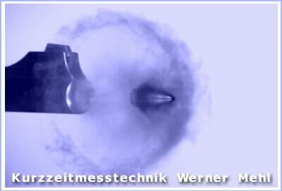
Fig 7. Bullet exiting the muzzle of a rifle. 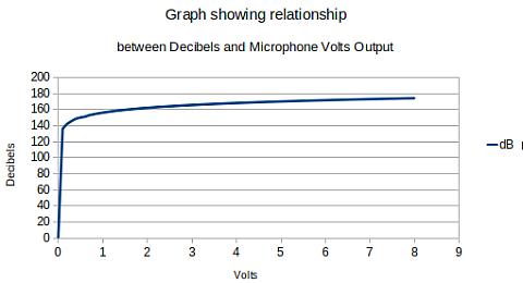
Fig 8.Graph of Decibels and Volts Output Research Methodology Plotting the Blast and Noise Emanating from the Rifle. Figure 4 illustrates the method employed by establishments such as Rockford Arsenal for measuring the blast and noise emanating from the muzzle of a rifle. This was initially attempted but was found to be far too time consuming. Additionally, it was suspected this method did not portray an accurate pictorial representation of the shape of the wave coming from the muzzle. As a consequence of advances in high speed digital photography, this has since been found to indeed be the case. Figure 7 provides a snapshot of a bullet departing the muzzle of a rifle. This photo was taken using equipment marketed by www.kurzzeit.com, a company specialising in the provision of truly exceptional cameras capable of video sequences at shutter speeds of one million frames per second. On that site, there are incredible videos of high velocity bullets "melting" into steel plates. |
Fig 9.A Plot of a plain muzzle compared to Method used to Depict Blast Patterns. Instead of graphing the blast per Figure 4, I decided to adopt the method shown in Figure 9, where the volts of microphone output are measured at a set distance from the muzzle in increments of 400 mils(22.5°). In this figure, the plot derived from a plain muzzle, shown as a dotted line, compared to a muzzle fitted with a short plain attachment (called Attachment 0), shown in a full line, is provided. This attachment provides a very short tube where there is a small clearance between it and the bullet. From this, it can be seen that the blast directly to the front in both instances is diminished because the high pressure gas initially streams out of the barrel at a angle (as seen in the photograph in Figure 7.) because of the presence of the bullet. The effect of the attachment is to cause the blast to be slightly more to the side. Interestingly, the blast to the rear is slightly diminished. |
|
Muzzle Attachments to Determine Effect of Muzzle Geometry on Blast Patterns 
Fig 10.Attachments used to determine the effect of muzzle geometries on blast patterns. The objective was to determine ways by which the gas could be encouraged to move sideways and find its way into a sealed expansion chamber, in the form of a lightweight tube that was concentric to the barrel of the rifle. To evaluate the effect of differing muzzle attachment geometries on the shape of the blast emanating from the muzzle, I constructed a number of different nozzles (per Figure 10), the culmination of which was what came to be christened, "the Fluidic Diode" (Attachment 4 and 4a). Of interest, in 1972, high speed photography was a very specialised field and very expensive. It was made clear to me from the outset that ADE would not/could not provide that facility to me so we were left with trying to see the blast through the use of a microphone and measurements. If high speed photography had been available, it would have been possible to take this research to the point of producing an optimised device. |
|
TEST RESULTS 
Fig 11.Blast pattern created by Attachment 0 and Attachment 1. Test Results - Attachments 0 and 1 Figure 11 shows the resultant pattern produced by the attachments 0 and 1 depicted at the bottom of each pattern. Attachment 0 had a very short exit and clearance of around .002". Attachment 1 consists of a long plain tube with the same clearance around the round. In this instance, we know from high speed photographs that the gas behind the bullet would squeeze past it once there was some clearance available. This in fact is verified by the blast pattern which shows the blast is more directional towards the front. |
Fig 12.Blast pattern created by Attachment 2 and Attachment 2a. Test Results - Attachments 2 and 2a Figure 12 shows the resultant pattern produced by the attachments 2 and 2a depicted here at the bottom of each pattern. Attachment 2a and 2 had are similar to Attachments 0 and 1 except that their exits had a circumferential groove of .0625" radius. The purpose of this groove was to see if it disrupted the flow of gas exiting from the muzzle and caused it to disperse into a wider arc. If so, the thinking was that this could assist in making the gas collide with baffles and so allow shortening of the silencer. As can be seen, the blast pattern is quite different because of the circumferential groove. |
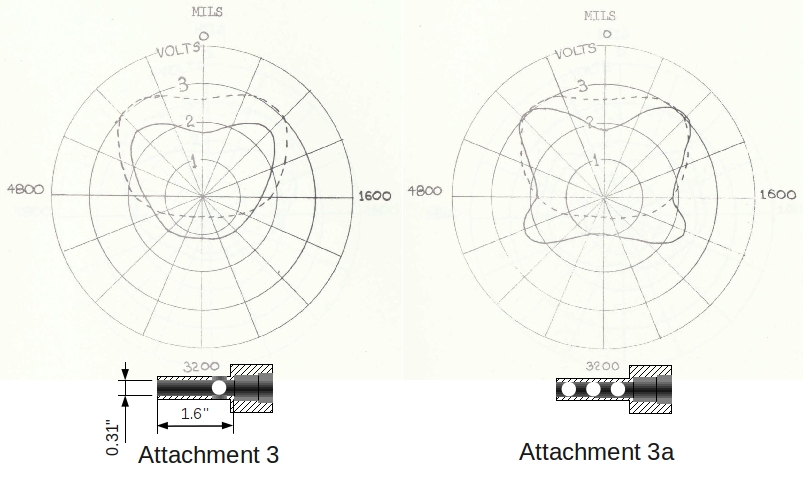
Fig 13.Blast pattern created by Attachment 3 and Attachment 3a. Test Results - Attachments 3 and 3a Figure 13 shows the resultant pattern produced by the attachments 3 and 3a depicted at the bottom of the pattern they produced. Attachment 3 had four holes close to the exit point of the bullet from the barrel. The blast is dissipated in four directions, hence the reason the blast is less in the horizontal plane that that which is produced by the 6 holes in attachment 3a. From this it can be deduced that the side holes are very effective in moving the blast out to the side. |
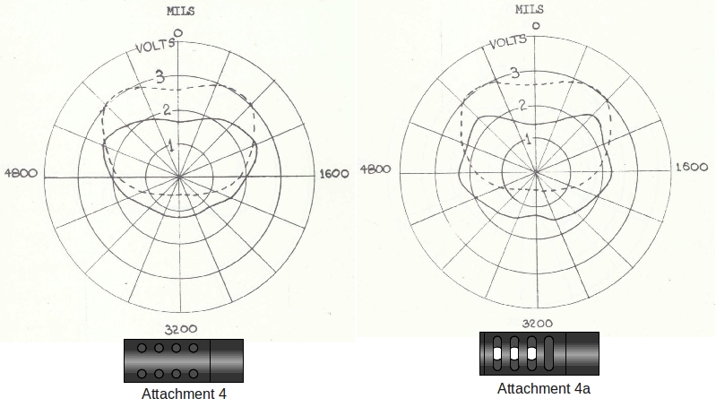
Fig 14.Blast pattern created by Attachment 4 and Attachment 4a. Test Results - Attachments 4 and 4a Figure 14 shows the resultant pattern produced by the attachments 4 and 4a depicted at the bottom of the pattern they produced. Attachment 4 and 4a contained the side passages that caused gas to bypass the bullet and then return back onto the main flow interfering with it escaping out the front of the nozzle. This momentary interference was designed to give a longer opportunity for the high pressure gas to enter the expansion chamber comprised of the concentric tube running back along the barrel of the weapon. Attachment 4 had 8 holes whereas 4a had slots which provided a better passage for gas to escape. This is evident in the blast diagrams. In the device where there are slots, the blast comes out the back far more sharply and the blast to the front is less intense. |
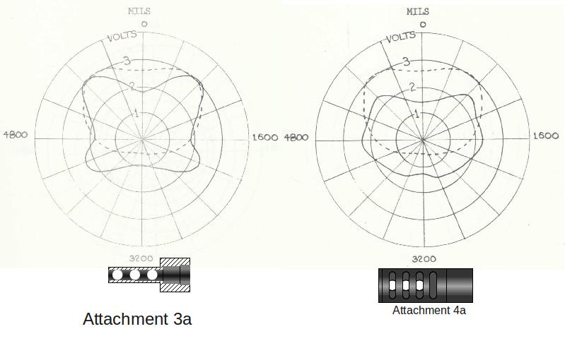
Fig 15.Comparison of Blast pattern created by Attachment 4a and Attachment 3a. Comparison of Attachment 4a to 3a Figure 15 shows the resultant pattern produced by the attachments 4a and 3a depicted at the bottom of the pattern they produced. Attachment 3a was the best performer of the nozzles without use of a gas diode. In these diagrams it can be seen that the gas diode throws the blast more out to the side than the 6 holes even though there are slats of metal interfering with the exit of the gas. For that reason, the final design of the gas diode went to extremes to ensure the sideways flow of the gas was impeded to the minimum extent possible. |
|
Fig 16. Use of an Adjustable Hood over Nozzles. Placing a "Hood" over the Nozzles The next step in this research consisted of placing an adjustable hood over the nozzles as shown in Figure 16. Unfortunately, as can be seen in Figure 8, the lack of range of the microphone did not allow accurate measurement of noise below 130dB. I had almost run out of time because of the approaching final year exams so it was not possible to pursue this matter much further. It was possible however to conduct some crude testing of the noise suppressor with a hood on it as depicted. Most probably contrary to all safety regulations and, on reflection now, common-sense, I stood downrange whilst a marksman, using the rifle locked in the test stand, fired rounds past me at a distance of around 75 metres. The report of the rifle was still substantial but of such magnitude that hearing protection did not seem to be necessary. The confusion caused by the muffled report was evident. Even at that close distance the echo of the bow-wave of the bullet bouncing off earth and trees caused you to have difficulty in determining the direction from where the "thump" of the rifle was coming. During this testing, the front of the hood blew off and went whizzing past me and things became a lot louder! It was at this point I decided this test was not such a bright idea!! (This is one of a number of lucky escapes from disaster I have had in my career as an inventor. For that reason, I am very forgiving of anyone who makes similar errors of judgement whilst trying hard to do their job to the best of their ability :-) |
|
THE FINAL DESIGN 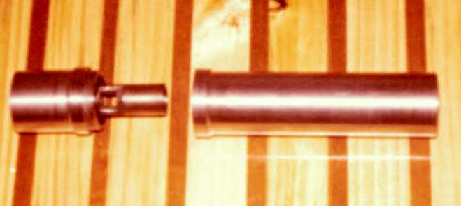
Fig 17.Partially disassembled Noise Suppressor showing the final diode. 3 Base Wksp Prototype Unfortunately, in the closing months of 1972, with final exams looming, I had run out of film and time and so it was not possible to build the final model. Instead, that was left to when I went on my first posting to 3 Base Workshop. At that workshop was Captain John Hempenstall. John was 3 years ahead of me at the Royal Military College. When we met at 3 Base Workshop, John was in charge of the General Engineering Company and he offered to make the prototype noise suppressor for me; a photo of which is shown in Figure 17. This suppressor reduced the noise from an L1A1 to around 85dB such that one could comfortably fire the weapon without the need for ear protection. The suppressor protruded about the same distance beyond the muzzle of the weapon as a conventional flash eliminator. |
|
A More Refined Design
Fig 18.Cross-Section of the final design of Silencer in disassembled state. The key to this idea working satisfactorily is to have the length of the bypass tubes such that, by the time the diverted gas returns to block the main flow, the bullet has managed to escape the ensuing turbulence. If that doesn't happen there is the possibility of the bullet being deflected, something that would adversely affect accuracy (and possibly result in the bullet clipping a baffle!), and/or the main shockwave will escape the weapon before the by-pass flow would collide with the main stream of gas. If this idea were to be taken further, it would be necessary that high speed photography be used to determine the length the by-pass passages have to be to ensure that the gas returned back on the main flow just after the bullet had left the nozzle. Doing that would optimise the effectiveness of the diode and ensure that the maximum amount of gas was diverted into the rearward expansion chamber. In Figure 18 the three main parts of the noise suppressor are depicted. At each opening, there is a circumferential groove to disrupt the flow of the gas in order to prevent it from forming a sharp jet which would give rise to a well defined shockwave. In the forward baffle assembly there is a sound absorbent material which also provides a rough seal to impeding on the movement of high pressure gas between baffle and the outer tube. The outer tube screws to the barrel by way of a very coarse Whitworth-like thread form to prevent sticking but nevertheless provides enough mechanical leverage to ensure the tube will stay on and that the parts are held firmly in axial alignment. The design is deliberately intended to be easy to clean and reasonably lightweight. Figure 19 is a snapshot of an animation drawn by a talented friend of mine, Phil Stonebanks. Phil builds light aircraft, runs a machine shop and can do amazing things with a 3D CAD package he bought a few years ago. If you click on the picture, you will see a full blown animation of another design of the silencer being assembled and then the bullet and shockwave making its way from the barrel to the outside atmosphere. Phil can be found at creativecad.com.au Optimised, this suppressor would reduce the report of the weapon to less than 85dB and make it very effective for sniping. If, through optimised design, it could be made to be lightweight, it would also be practical to use a device such as this on a General Purpose Infantry Rifle. Rejected by Army Design Establishment The prototype noise suppressor was submitted to Army Design Establishment for assessment under the auspices of the Army Suggestions Scheme. As with the infantry rifle (RMC No2), ADE could see no merit in the noise suppressor and even opined it would increase the noise to the firer. At that stage, I decided to stop pursuing the development of rifles and noise suppressors and instead concentrate on other things such as family and a physiotherapy table for a friend's daughter who was suffering from Cystic Fibrosis. |
|
CONCLUDING COMMENTS Use of Silencers on Sniper Rifles 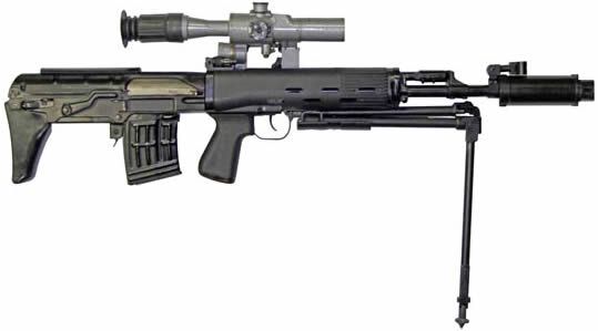
Fig 19.The Dragunov sniper rifle fitted with The Australian Defence Force uses a number of different types of noise suppressor with its sniper rifles; one of which, procured from an overseas company, utilises a noise suppressor design very similar to that which is described here. One of the most exceptional sniper rifles produced in recent times is the Dragunov, depicted in Figure 19. It is one of the few sniper rifles capable of automatic fire and it has a bull-pup butt design. This weapon is all the more extraordinary because it uses a similar locking action to the AK-47, an action not normally associated with a weapon capable of high accuracy. |